
Extreme Bearing Installation on an Adapter Sleeve (Spherical Roller & Self-Aligning Bearings)
Mounting a bearing with an adapter sleeve is technically one of the best mounting methods, providing a secure fit and excellent load-carrying performance. However, installation should be carried out by a qualified technician.
Before starting the installation, carefully read the mounting instructions and ensure that all required tools and components are available. Then follow the mounting procedure step by step to ensure correct bearing positioning, proper fit, and reliable operation.
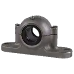
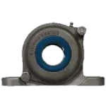
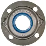
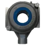
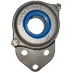
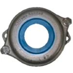
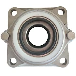
- Housing
- Cover
- Cover seal
- Back seal
- Bearing
- Adapter sleeve
- Locating ring
- Oring
- Bolts
- Grease nipple

Preparations Prior to Mounting
Before mounting the bearing, ensure that the shaft is within the specified tolerance. An out-of-tolerance shaft may cause the adapter sleeve to deform the bearing inner ring, resulting in reduced bearing performance and service life.
- Ensure that the shaft is clean and free from burrs, particularly those caused by set screws. Remove any burrs using a fine file. We recommend using a fine file rather than emery cloth, as this removes only the high spots without affecting the overall shaft tolerance.
- Verify that the bearing seat diameter is within tolerance. Measurements should preferably be taken at three cross-sections, spaced approximately 20 mm apart, across the bearing seating area.
- The recommended shaft tolerance is h9. For shaft diameters Ø35 mm to Ø40 mm, the tolerance range is +0.000 / -0.062 mm.
- Check the shaft cylindricity using a micrometer at three positions around the circumference. The cylindricity tolerance should comply with IT5, with a maximum deviation of 0.011 mm.

- Ra = 0.4 to 0.8 mm
- CLa = 8 to 25 mm
- Rz = 1.0 to 4.0 mm
- Rmax ≤ 6.3 mm
- Ensure that the shaft and adapter sleeve contact surfaces are clean, dry, and free from grease, oil, dirt, or contamination.
- Clean the support surfaces thoroughly and inspect them for damage, scratches, dents, or other surface imperfections that could affect mounting accuracy.
Built-in Clearance: A Unique Engineering Advantage
An Extreme Bearing assembly provides built-in clearance to accommodate thermal expansion and contraction in your machine design, ensuring reliable bearing performance under varying operating temperatures.
An Extreme Bearing Unit offers a unique advantage over conventional mounted bearing units. The units are supplied with an FRB locating ring, allowing the bearing arrangement to be configured either as a locating bearing, restricting axial displacement, or as a non-locating bearing, permitting axial movement to accommodate shaft expansion. This provides greater flexibility in bearing arrangement design and ensures accurate shaft positioning, controlled thermal expansion, and improved system reliability.
For optimal bearing performance and service life, it is essential to consider thermal expansion and contraction during the design phase.
-
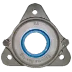
Installation of the FRB Locating Ring
All Extreme Bearing Units are supplied with an FRB locating ring as standard.
In a typical bearing arrangement, one bearing unit is configured as the locating bearing and the other as the non-locating (floating) bearing:
- Locating side: Install the FRB locating ring to prevent axial displacement of the bearing within the housing.
- Floating side: Do not install the FRB locating ring. This allows the bearing to move axially and accommodate thermal expansion of the shaft.
Since every Extreme Bearing Unit is supplied with an FRB locating ring, installing a bearing pair will normally result in one unused FRB ring. This spare ring may be retained for future use or disposed.

Allow for Thermal Expansion and Contraction
The total clearance available for thermal expansion and contraction is equal to the thickness of the locating ring. Material expansion and contraction must be taken into account to ensure that sufficient clearance remains for proper bearing operation.
In the diagram, clearance C represents the available movement for contraction due to cooling, while clearance B represents the available movement for expansion due to heating.
The table below shows the maximum permissible values for C and B, depending on the shaft diameter.


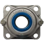
Step-by-Step Assembly Guide for a Stainless Steel 316 Extreme Bearing Unit with an Adapter Sleeve
- Put some grease on the seal lip.
- Position both bearing units onto the shaft and bolt the bearing housing to the machine frame but do not tighten the bolts all the way yet.
- Check if the shaft has the correct level on the machine frame.
- Tighten the attachment bolts of the bearing housing to the frame.
- Measure unmounted radial internal clearance with

Step 6 is unique because two different mounting methods can be used, depending on the application and positioning requirements.
Method 1 is the most commonly used mounting method and is suitable for the majority of applications.
Method 2 is intended for applications where a more precise bearing position is required. However, when highly accurate positioning is critical, a cylindrical bore mounting arrangement is generally recommended instead of an adapter sleeve. Adapter sleeve mounting can achieve accurate positioning, but the procedure is more delicate and requires careful execution.


11. During tightening of the KM lock nut, the bearing will be driven axially inward on the tapered seat of the adapter sleeve. If possible, the reduction in internal bearing clearance should be measured and checked by comparing the clearance before and after tightening the KM lock nut.
Verifying the clearance reduction helps ensure that the bearing has been mounted correctly and that the required interference fit has been achieved.


12. Place the locating ring in position and then screw on the locking nut with its chamfer side facing the bearing.
13. Make sure that the O-ring is mounted properly.
14. Check that the shaft is not too long in case you want to use a closed cover seal. If you have a bearing for a drive situation, use an open cover with a shaft seal. In that case, put some grease on the seal lip and carefully push the seal over the shaft
15. If Method 1 was selected in Step 6, the shaft and bearing assembly should have approximately 1 mm of axial clearance in the backward direction when mounted on the locating (fixed) side.
If your application requires Method 2, where highly accurate axial positioning is necessary, verify the final bearing position after mounting. If the axial displacement exceeds the permissible limit, reverse Steps 6–14, adjust the bearing position as required, and repeat the mounting procedure.

17. Fill the Bearing Unit with Grease
The bearing unit must now be filled with grease.
Slowly pump grease into the bearing unit while rotating the shaft or bearing by hand. Continue greasing until fresh grease begins to pass gradually through the seals without air pockets.
Do not pump the grease too quickly. Excessive greasing speed can trap air inside the bearing unit, causing grease to be forced out through the seals before the bearing is completely filled.
Proper grease filling is important to ensure adequate lubrication, prevent premature wear, and maximize bearing service life.
What is the recommended lubricant for the Extreme bearings?
As a bearing supplier, we cannot provide a definitive lubrication recommendation for every application. The most appropriate approach is to consult your grease supplier, as the selection of the correct lubricant depends on a variety of operating conditions.
Since the bearings used in our units are standard roller bearings, the lubrication requirements can vary significantly depending on the specific application. In addition, industry-specific requirements may need to be considered, such as FDA-approved greases for food processing applications or lubricants suitable for cleanroom environments.
The following factors should be considered when selecting a lubricant:
- Temperature fluctuations – Bearings exposed to extreme heat or cold may require specialized lubricants to maintain performance.
- RPM (rotational speed) – High-speed applications demand a grease capable of handling heat generation, while low-speed applications may require lubricants that remain effective under minimal movement.
- Duty cycle – Intermittent versus continuous operation can influence the lubrication requirements.
- Applied loads – Both axial and radial loads affect grease performance and service life.
- Vibration and misalignment – These conditions can accelerate grease degradation or cause lubricant displacement from critical contact areas.
- Environmental conditions – The operating environment, such as desert, underwater, offshore, or humid industrial applications, has a significant impact on lubricant performance and durability.
- Compatibility with surrounding materials – The grease must be compatible with seals, elastomers, and other system materials to prevent deterioration or failure.
- Chemical exposure – Applications involving aggressive chemicals, cleaning agents, or process fluids may require chemically resistant lubricants.
- Humidity and moisture – Wet environments, particularly those involving freshwater, seawater, or frequent washdowns, require highly water-resistant greases.
- Maintenance intervals – The availability of maintenance resources and the required relubrication intervals should be considered when selecting a lubricant.
In conclusion, the optimal lubrication solution depends on your operating conditions, environment, and performance requirements. We therefore recommend consulting your grease supplier to ensure that all relevant factors are taken into account and that the most suitable lubricant is selected for your application. Proper lubricant selection is essential for achieving maximum bearing performance and service life.