
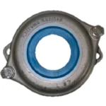
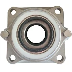
Axial clearance – A Key Advantage
preserving optimal internal clearance.
Axial play within the housing absorbs thermal expansion and structural deflection under heavy loads. Configuring one bearing position as non-locating (free) retains this play, preventing rolling element binding and preserving optimal internal clearance.”
Extreme Bearings: A Unique Engineering Advantage – Built-In Clearance
The seats of an Extreme Bearing are machined to a tolerance in order to provide a loose fit. The bearing seats in the housings are sufficiently wide to allow the bearing axial displacement and likewise to accommodate for thermal expansion of the shaft due to high temperatures.
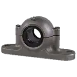
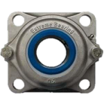
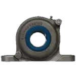
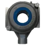
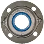
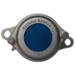
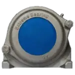
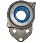
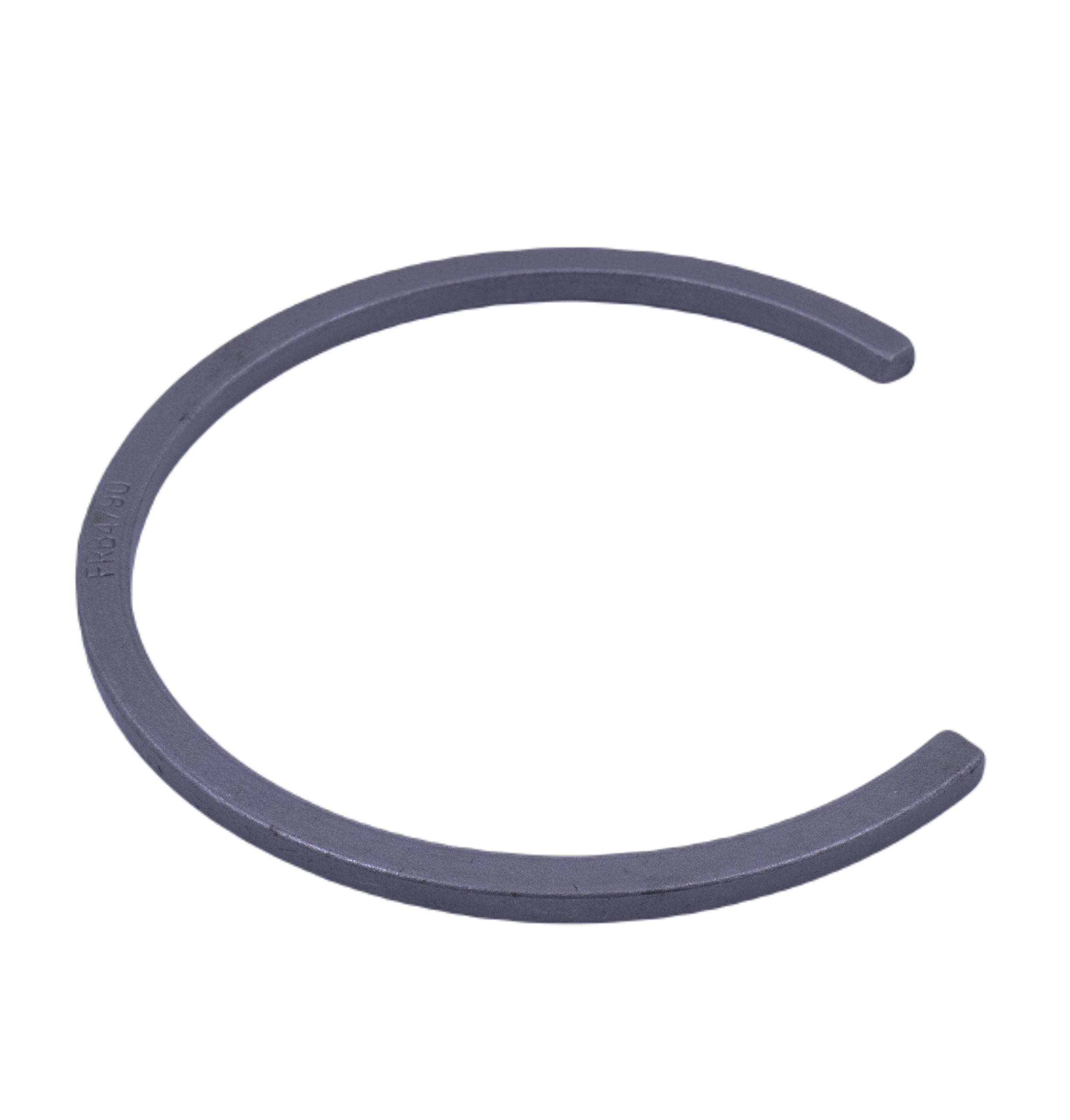
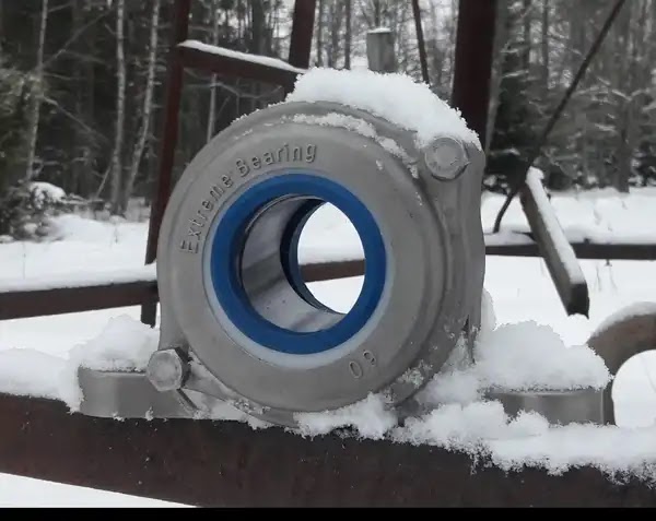
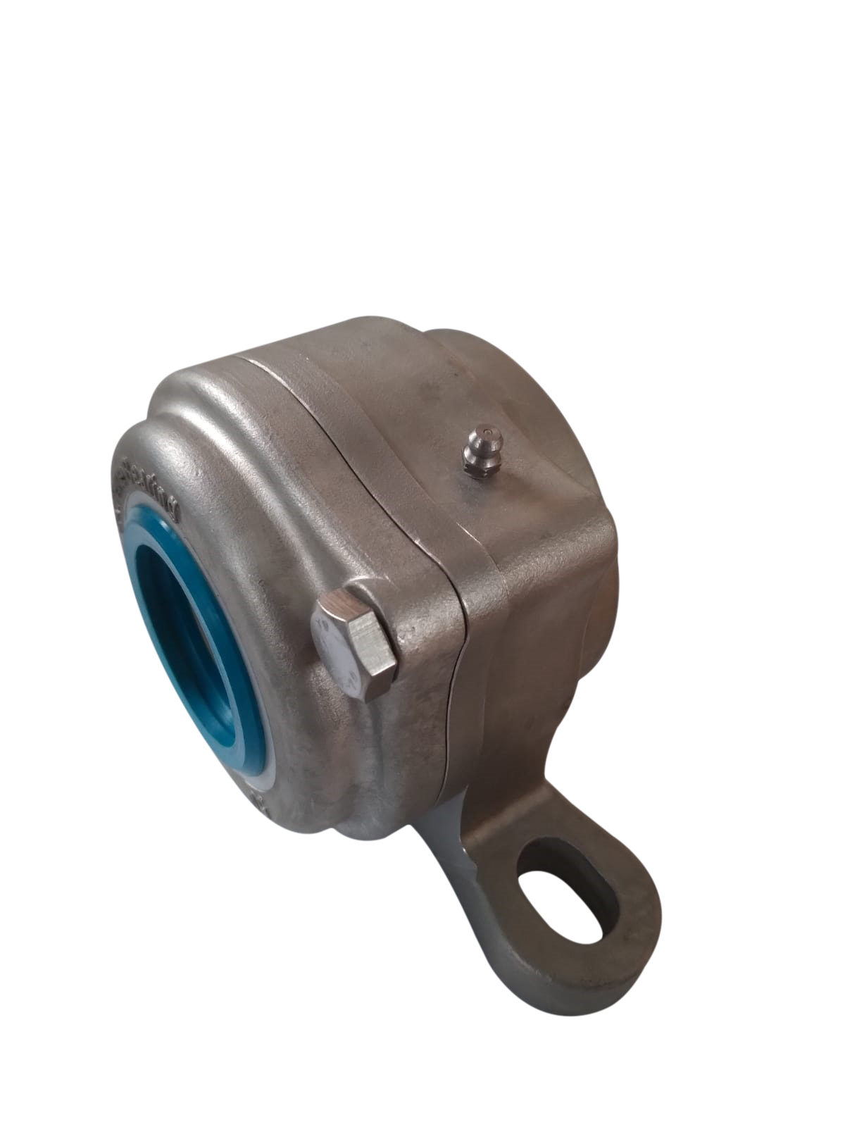
An Extreme Bearing Unit offers a unique advantage over conventional mounted bearing units. The units are supplied with an Locating ring, allowing the bearing arrangement to be configured either as a locating bearing, restricting axial displacement, or as a non-locating bearing, permitting axial movement to accommodate shaft expansion. This provides greater flexibility in bearing arrangement design and ensures accurate shaft positioning, controlled thermal expansion, and improved system reliability.
Expansion clearance in standard Extreme Bearings configurations
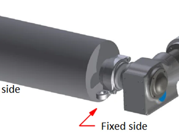
Standard Extreme Bearing units provide thermal expansion clearance equal to the thickness of the locating ring. When operating temperature differences occur between the shaft and the support structure, thermal expansion and contraction must be accounted for to preserve optimal internal bearing clearance.
Additionally, structural deflection or bending under heavy loads can consume bearing clearance, potentially leading to rolling element binding. Therefore, it is best practice to configure one bearing as a non-locating (free) bearing to retain adequate axial movement.
Calculating Maximum Shaft Length for standar extreme bearings
Operating temperatures directly affect the required shaft length. When installing long shafts, you must calculate thermal expansion or contraction and adjust bearing positions accordingly.
-
Stainless Steel: Expands by ~0.016 mm per metre for every 1°C temperature rise.
-
Carbon Steel: Expands by ~0.012 mm per metre for every 1°C temperature rise.
The table shows the allowable shaft length (m) based on the temperature difference between the shaft and the support structure. Longer shafts or higher temperatures require greater internal axial movement in the housing to maintain optimal clearance for the rolling elements
"Keep in mind that a 50°C temperature difference can occur very quickly. For example, if a machine operates in winter conditions at -10°C and a hot product warms the conveyor drum shaft to +40°C, you immediately reach a 50°C differential."
| Shaft Ø (mm) | Max. Play (mm) | Material | 50°C | 100°C | 150°C | 200°C | 250°C |
| 20 – 40 | 3.5 | Carbon Steel | 5.83 | 2.92 | 1.94 | 1.46 | 1.17 |
| 20 – 40 | 3.5 | Stainless Steel | 4.38 | 2.19 | 1.46 | 1.09 | 0.88 |
| 45 – 60 | 4.0 | Carbon Steel | 6.67 | 3.33 | 2.22 | 1.67 | 1.33 |
| 45 – 60 | 4.0 | Stainless Steel | 5.00 | 2.50 | 1.67 | 1.25 | 1.00 |
| 70 – 80 | 5.0 | Carbon Steel | 8.33 | 4.17 | 2.78 | 2.08 | 1.67 |
| 70 – 80 | 5.0 | Stainless Steel | 6.25 | 3.13 | 2.08 | 1.56 | 1.25 |
| 100 | 10.0 | Carbon Steel | 16.67 | 8.33 | 5.56 | 4.17 | 3.33 |
| 100 | 10.0 | Stainless Steel | 12.50 | 6.25 | 4.17 | 3.13 | 2.50 |
Flexible Locating and Floating Design
Extreme Bearing Units can be used in both locating and floating bearing positions within the same system. In a typical arrangement with two opposing bearing units, shaft expansion due to temperature changes is safely accommodated by allowing one bearing to move axially.
This flexibility is achieved through the use of an FRB locating ring:
- Locating position: The locating ring is installed to prevent axial displacement of the bearing within the housing, ensuring precise axial positioning of the shaft.
- Floating position: The locating ring is omitted, allowing axial movement of the bearing to compensate for thermal expansion and prevent internal stress build-up.
Each unit is delivered with an locating ring
Each Extreme Bearing Unit is delivered with an locating ring as standard. This allows every unit to be configured either as a locating or floating bearing, depending on the application requirements.
In a paired installation, one locating ring typically remains unused. This can be stored as a spare part or discarded if not required, helping to reduce inventory complexity and simplify stock management.
Taken into acount during the engineering phase
For optimal bearing performance and maximum service life, thermal expansion and contraction must be taken into account during the engineering phase of the machine design.
Calculate the maximum shaft length depending on the temperature in your application. In case you need to mount a long shaft, it is necessary to calculate the thermal expansion or contraction and adjust the bearing position to take this into account. As an example, a stainless steel shaft of 1 metre will become 0.023 mm longer when the temperature rises by 1°C and a carbon steel shaft of 1 metre will become 0.016 mm longer when the temperature rises by 1°C. The table shows the maximum shaft length depending on how the temperature changes during operation after the time of installation.
The total axial bearing unit clearance
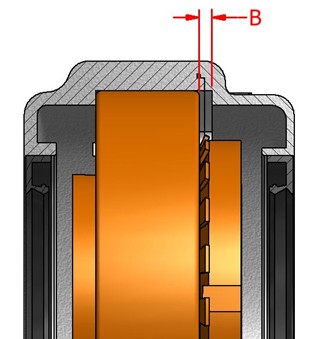
The total axial bearing unit clearance available for thermal expansion and contraction is equal to the thickness of the locating ring. Material expansion and contraction must be taken into account to ensure that sufficient clearance remains for proper bearing operation.
In the diagram, clearance C represents the available movement for contraction due to cooling, while clearance B represents the available movement for expansion due to heating.
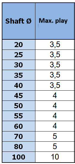
The table below shows the maximum permissible values for C and B, depending on the shaft diameter.


| Shaft Ø | C, Max. Cooling shrinkage mm | B, Max. Heating expansion mm |
| 20 | 3,5 | 3,5 |
| 25 | 3,5 | 3,5 |
| 30 | 3,5 | 3,5 |
| 35 | 3,5 | 3,5 |
| 40 | 3,5 | 3,5 |
| 45 | 4 | 4 |
| 50 | 4 | 4 |
| 55 | 4 | 4 |
| 60 | 4 | 4 |
| 70 | 5 | 5 |
| 80 | 5 | 5 |
| 100 | 10 | 10 |
Extra room for more axial displacement
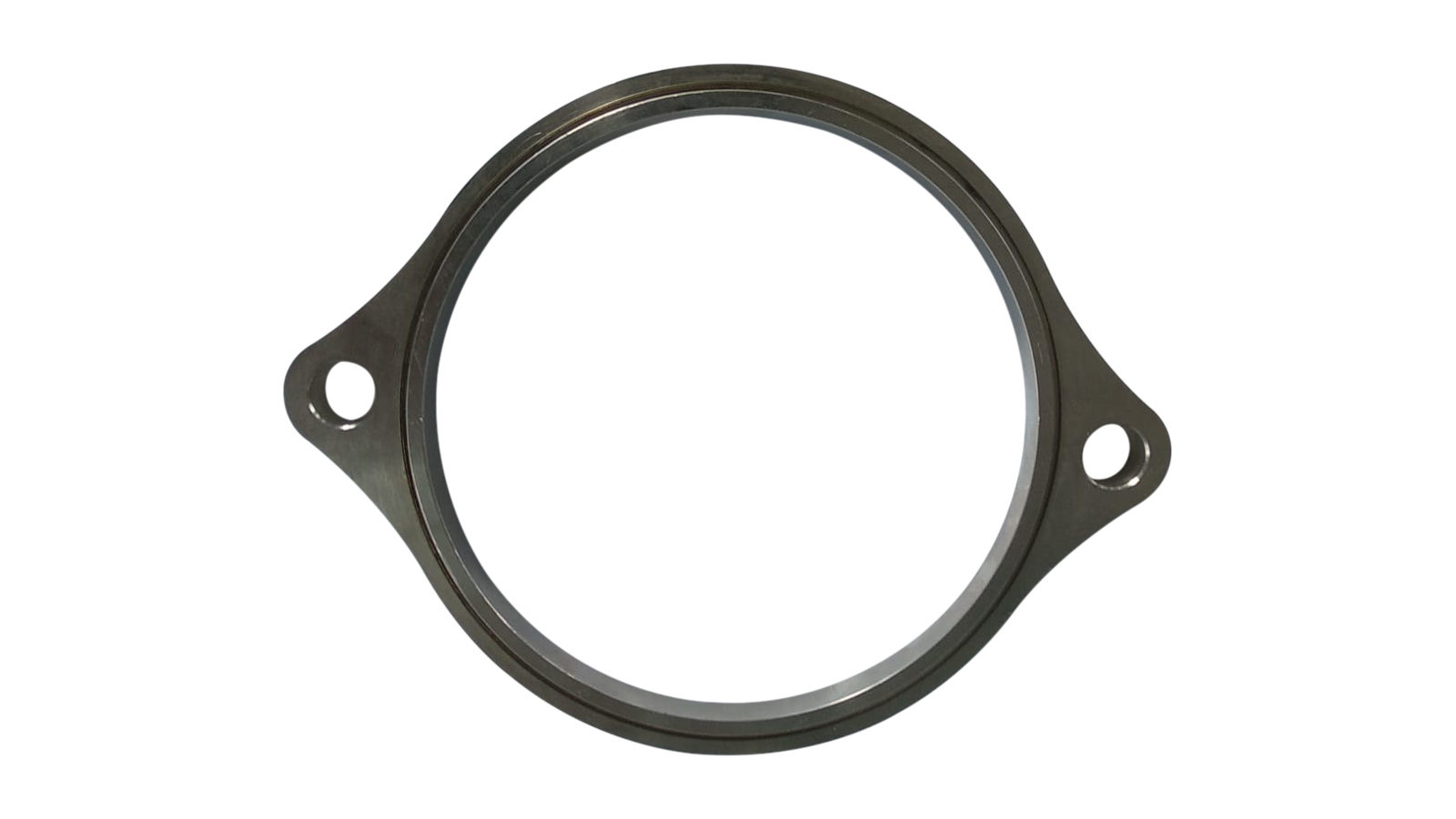
It is possible that the standard option in our Extreme bearings is not sufficient, because your construction has very long shafts, large temperature difference or other causes. in this case we supply an extra extension ring that fits between the bearing unit and the cap.
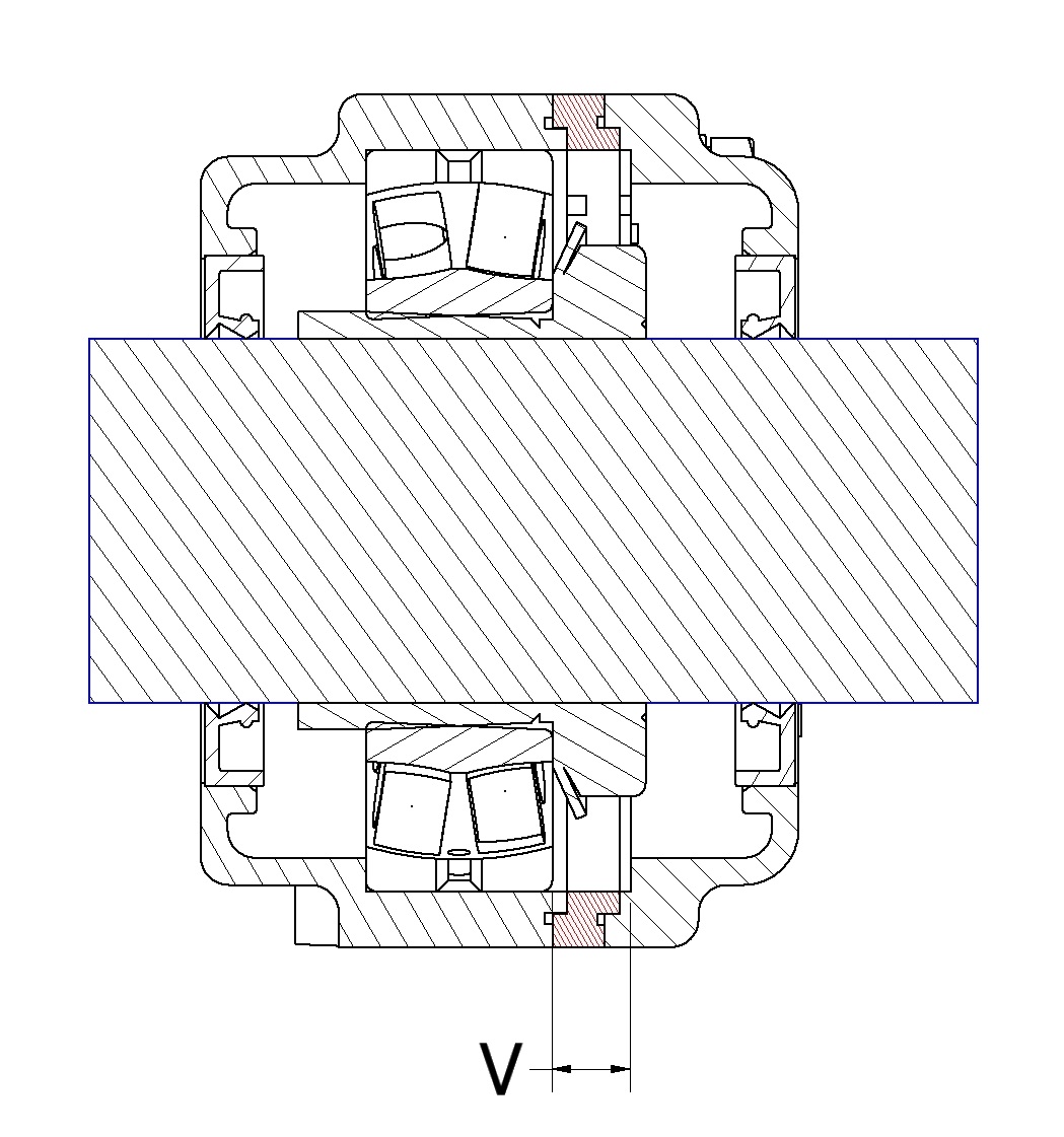
| Size | V |
| 20 | 8.5 |
| 25 | 8.5 |
| 30 | 8.5 |
| 35 | 8.5 |
| 40 | 8.5 |
| 45 | 11 |
| 50 | 11 |
| 55 | 11 |
| 60 | 11 |
| 65 | 13 |
| 70 | 13 |
| 75 | 13 |
| 80 | 18 |
| 85 | 18 |
| 90 | 20 |
| 100 | 20 |

Linear displacement through the bearing unit
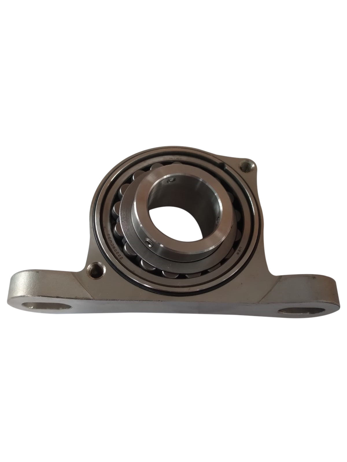
A situation can arise where extreme axial displacement is required or a linear movement is required through the bearing unit. For this situation you can choose an Extreme Bearing with a Cylindiche bore without a locking adapter
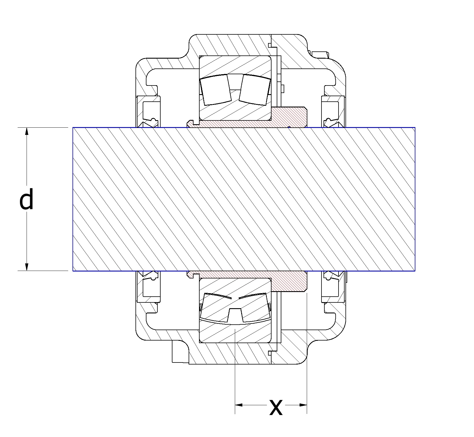

Tip: To ensure that the shaft does not rotate in the bearing, a keyway can be made in the shaft.
Tipcal customer requests reagarding this page were
Extreme Bearing could help out!
Good afternoon,
We have an issue in one installation of our tipping buckets, where we have installed your bearings. We have 3 tipping buckets installed in a storm tank, each is suspended from 2 bearings. Tipping bucket is an element to clean the surface of storm tanks. When a storm happens, the storm tank is filled by water, and after the storm, once it is empty, it is necessary to clean the surface due to the sediments.
Tipping buckets are filled with water, and when they are full, they tip due to their geometry, and make a wave to clean the surface. The issue is the following: We have all the bearings tighten to the axis, and we found that the buckets are moving horizontally through the bearings.
Do you know how it can be possible?
Your assistance is appreciated!