
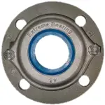
SS-316 4-Bolt Flange Bearing Housings
Four Hole Flanged Stainless Housing
EXF – 4-bolt flanged
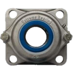
Four-bolt square flanged Extreme Bearing housing designed for mounting on flat machine surfaces. Manufactured from rigid cast AISI 316 stainless steel, with configurable bearing inserts and sealing options for a wide range of applications.
Like all Extreme Bearing housings, the EXF 4-Hole Flange model is engineered for demanding environments with durable AISI 316 stainless steel for superior corrosion resistance and reliability. The EXF provides a rigid four-hole flange mounting solution for parallel shaft applications, ideal for gearmotor adapters, conveyor frames, and tank agitator systems.
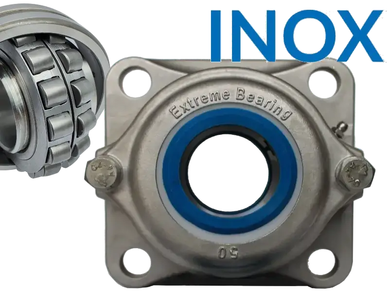
View the EXF 4-bolt flange housing in 3D
Explore the stainless steel 316 EXF 4-bolt flange housing in an interactive 3D environment. You can rotate, zoom, and measure the model directly to gain a clear understanding of the housing dimensions and design features.
The 4-bolt square design provides excellent stability
Stronger mounting stability
Four bolts hold the housing more securely than two bolts.
- Less vibration
- Reduced movement
- Better resistance to twisting forces
This is important in high-speed or heavy-duty machinery.
Better load distribution
The square pattern spreads forces evenly around the shaft.
Compared to a 2-hole flange:
- Lower stress on mounting bolts
- Better support for heavier radial loads
- Improved housing stability
Tensioner stud
The EXF bearing unit is provided with a tensioner stud. This is a unique feature of this type of Extreme Bearing. This feature can be very helpful when designing a conveyor belt.
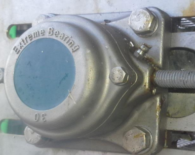
Discover our exceptional sealing options
Configurable sealing solutions protect the bearing against water, dust, dirt, and other contaminants — for washdown, submerged, and abrasive applications.
Technical Datasheet
EXF – Stainless Steel 316 4-Bolt Flange Housing
Technical Specifications
| Specification | Description |
|---|---|
| Product | Stainless Steel 316 4-Bolt Flange Housing |
| Type | EXF |
| Mounting style | 4-bolt square flange |
| Shaft sizes | 25 mm – 100 mm, including standard inch sizes |
| Special feature | Integrated tensioner stud for conveyor belt tensioning |
| Housing material | Stainless Steel 316 (AISI 316 / UNS S31600) |
| Construction | Heavy duty |
| Application | Industrial machinery |
| Configuration | Extreme Bearing Product Chooser |
| Target market | OEMs, Machine Builders & System Integrators |
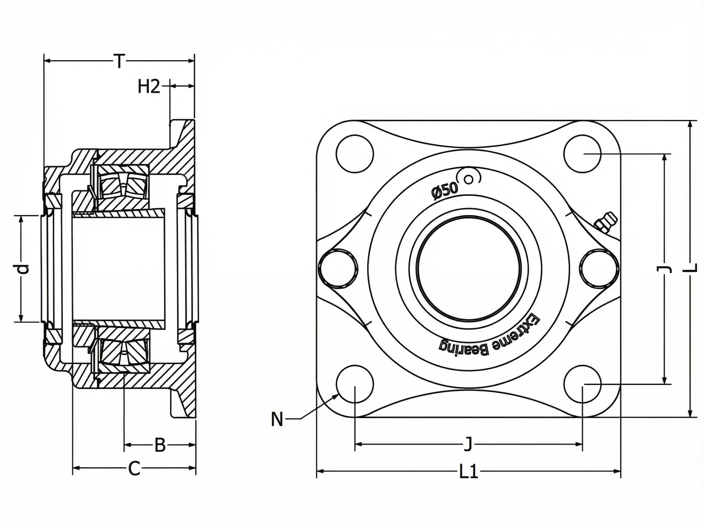
EXF 4-Bolt Flange Housing Dimensions and Mounting Specifications
J is the bolt hole pitch circle diameter (mm) — the distance between opposing bolt centres, used when laying out the four mounting holes on the machine face.
Load Directions for the EXF 4-Bolt Flange Housing
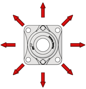
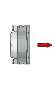
4-hole flange mounted Extreme Bearing units are designed to handle radial loads and forces acting vertically toward the mounting surface. When radial loads are applied from other directions, the bolt connection to the machine frame becomes the limiting factor and must be checked to ensure the load remains within the permitted limits.
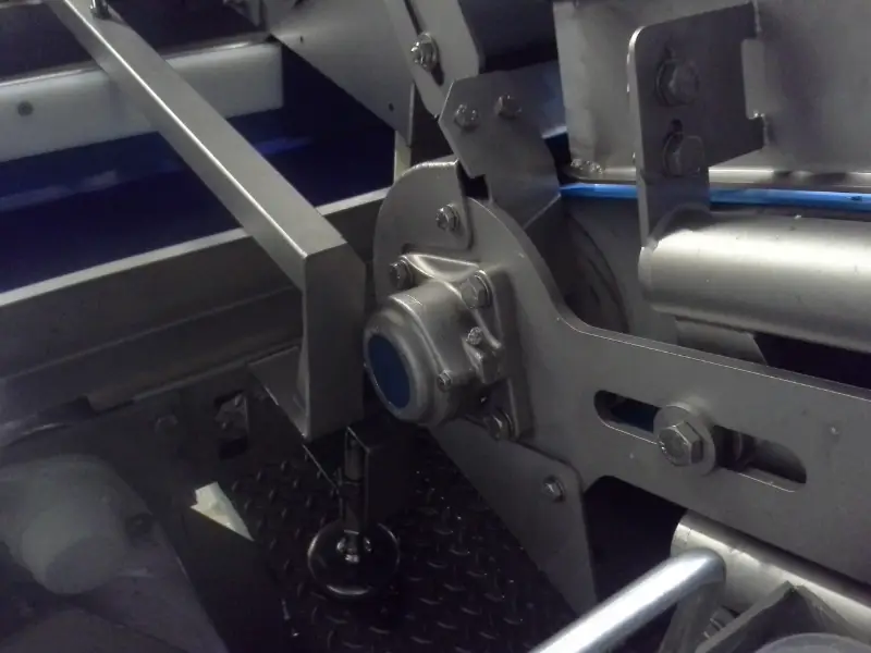
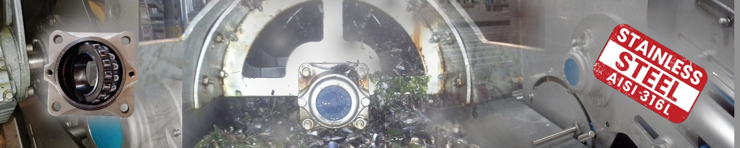
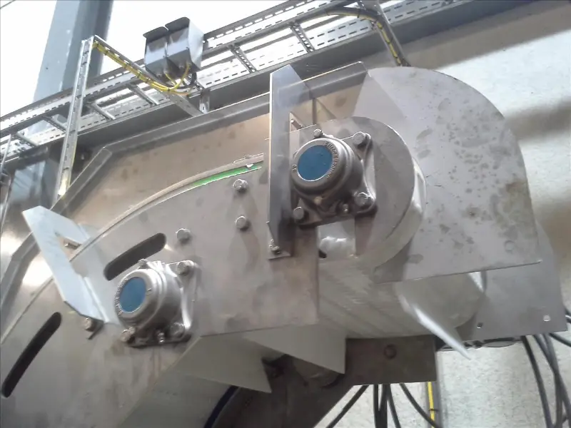
Bearing the unbearable — a look into the world of Extreme Bearing Type EXF applications.

Ready to build your bearing assembly?
Configure your stainless steel 316 EXF 4-bolt flange housing in the Product Chooser and download the Technical Datasheet (PDF) and 3D STEP model instantly.