DOWNLOAD PDF
Download the complete mounting instructions as a PDF for offline reference and print.
Download PDF
Parts Overview
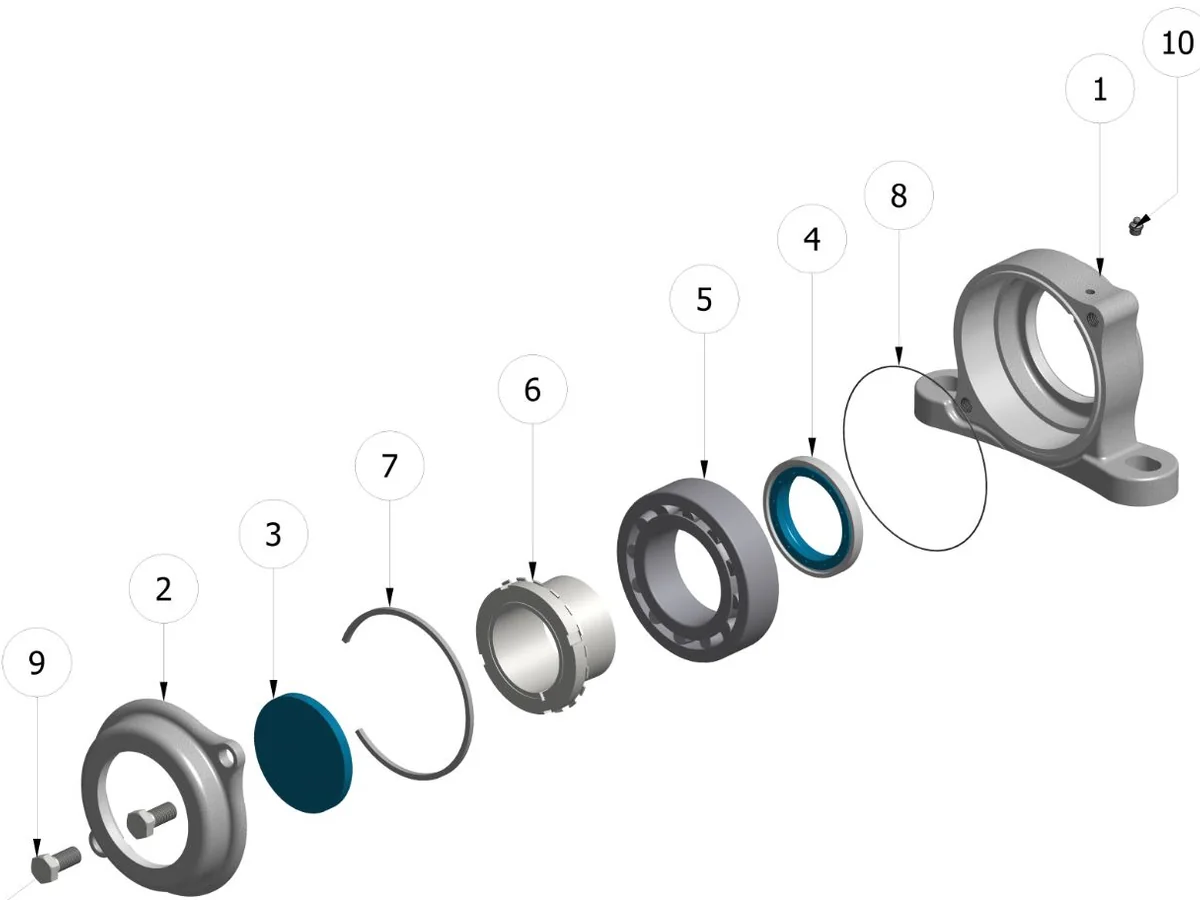
Each Extreme Bearing unit consists of the following components:
- Housing - Main bearing housing (stainless steel 316)
- Cover - Front cover plate
- Cover seal - Seal on cover side
- Back seal - Seal on housing side
- Bearing - Spherical roller bearing
- Adapter sleeve - For shaft mounting
- Locating ring - Axial positioning
- O-ring - Additional sealing
- Bolts - Cover attachment
- Grease nipple - For lubrication
Points to Consider Prior to Mounting
1. Check the Tolerance of the Shaft
The shaft should be clean, dry and free from grease.
Make sure that the shaft is free of any surface damage such as burrs from set screws and scratches. If not, remove the burrs and scratches with a fine file. We prefer a fine file over emery cloth so that you only take away the high spots without affecting the main shaft tolerance.
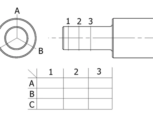
Check if the shaft bearing seat is within tolerance, preferably at three cross-sections 20 mm apart in the position where the bearing will be placed. These positions are shown as 1, 2 and 3 in the diagram and three measurements should be taken around the cross-section at A, B and C.
2. Check the Hardness and Surface Roughness of the Shaft
The hardness of the shaft should be a minimum of HRc 55. In general, shafts of carbon steel or stainless steel are most suitable. What's even more important than a correct interference fit of the oil seal, is a perfectly smooth shaft in the region of the seal.
For normal circumstances, the shaft in the region of the seal must have a surface roughness of approximately:
| Parameter | Value |
|---|---|
| Ra | 0.4 to 0.8 μm |
| CLa | 8 to 25 μm |
| Rz | 1.0 to 4.0 μm |
| Rmax | ≤ 6.3 μm |
3. Decide on the Fixed Side
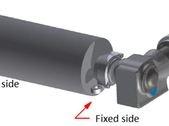
Each shaft will have a fixed bearing location (mounted first) and a floating location (mounted second).
If an Extreme Bearing is to be used on a drive shaft, it is required that the fixed side be the motor drive side. To minimize the risk of any confusion, we strongly recommend the fixed side be the drive side, as depicted in the diagram.
4. Allow for Thermal Expansion and Contraction
There is a total clearance available for thermal expansion that is equal to the thickness of the location ring. The expansion and contraction of material must be considered in order to maintain the clearance that is required to operate the bearing well.
In the diagram, the clearance for contraction by cooling is indicated by C and the clearance for expansion by heating is indicated by B.
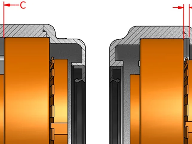
The table shows the maximum values for C and B depending on the diameter of the shaft:
| Shaft Ø (mm) | C, Max. Cooling shrinkage (mm) | B, Max. Heating expansion (mm) |
|---|---|---|
| 20 | 3.5 | 3.5 |
| 25 | 3.5 | 3.5 |
| 30 | 3.5 | 3.5 |
| 35 | 3.5 | 3.5 |
| 40 | 3.5 | 3.5 |
| 45 | 4 | 4 |
| 50 | 4 | 4 |
| 55 | 4 | 4 |
| 60 | 4 | 4 |
| 70 | 5 | 5 |
| 80 | 5 | 5 |
| 100 | 10 | 10 |
Calculate the maximum shaft length depending on the temperature in your application. In case you need to mount a long shaft, it is necessary to calculate the thermal expansion or contraction and adjust the bearing position to take this into account.
Thermal expansion examples:
- A stainless steel shaft of 1 metre will become 0.023 mm longer when the temperature rises by 1°C
- A carbon steel shaft of 1 metre will become 0.016 mm longer when the temperature rises by 1°C
Maximum Shaft Length by Cooling Contraction
Values in meters per degrees Kelvin/Celsius temperature change:
| Shaft (mm) | 10C | 20C | 40C | 50C | 60C | |||||
|---|---|---|---|---|---|---|---|---|---|---|
| SS | Steel | SS | Steel | SS | Steel | SS | Steel | SS | Steel | |
| 20 | 9.38 | 12.50 | 4.69 | 6.25 | 2.34 | 3.13 | 1.88 | 2.50 | 1.56 | 2.08 |
| 25 | 9.38 | 12.50 | 4.69 | 6.25 | 2.34 | 3.13 | 1.88 | 2.50 | 1.56 | 2.08 |
| 30 | 9.38 | 12.50 | 4.69 | 6.25 | 2.34 | 3.13 | 1.88 | 2.50 | 1.56 | 2.08 |
| 35 | 9.38 | 12.50 | 4.69 | 6.25 | 2.34 | 3.13 | 1.88 | 2.50 | 1.56 | 2.08 |
| 40 | 9.38 | 12.50 | 4.69 | 6.25 | 2.34 | 3.13 | 1.88 | 2.50 | 1.56 | 2.08 |
| 45 | 9.38 | 12.50 | 4.69 | 6.25 | 2.34 | 3.13 | 1.88 | 2.50 | 1.56 | 2.08 |
| 50 | 9.38 | 12.50 | 4.69 | 6.25 | 2.34 | 3.13 | 1.88 | 2.50 | 1.56 | 2.08 |
| 55 | 9.38 | 12.50 | 4.69 | 6.25 | 2.34 | 3.13 | 1.88 | 2.50 | 1.56 | 2.08 |
| 60 | 9.38 | 12.50 | 4.69 | 6.25 | 2.34 | 3.13 | 1.88 | 2.50 | 1.56 | 2.08 |
| 70 | 18.75 | 25.00 | 9.38 | 12.50 | 4.69 | 6.25 | 3.75 | 5.00 | 3.13 | 4.17 |
| 80 | 18.75 | 25.00 | 9.38 | 12.50 | 4.69 | 6.25 | 3.75 | 5.00 | 3.13 | 4.17 |
| 100 | 14.38 | 19.17 | 7.19 | 9.58 | 3.59 | 4.79 | 2.88 | 3.83 | 2.40 | 3.19 |
Maximum Shaft Length by Heating Expansion
Values in meters per degrees Kelvin/Celsius temperature change:
| Shaft (mm) | 10C | 20C | 40C | 50C | 60C | |||||
|---|---|---|---|---|---|---|---|---|---|---|
| SS | Steel | SS | Steel | SS | Steel | SS | Steel | SS | Steel | |
| 20 | 12.50 | 16.67 | 6.25 | 8.33 | 3.13 | 4.17 | 2.50 | 3.33 | 2.08 | 2.78 |
| 25 | 12.50 | 16.67 | 6.25 | 8.33 | 3.13 | 4.17 | 2.50 | 3.33 | 2.08 | 2.78 |
| 30 | 12.50 | 16.67 | 6.25 | 8.33 | 3.13 | 4.17 | 2.50 | 3.33 | 2.08 | 2.78 |
| 35 | 12.50 | 16.67 | 6.25 | 8.33 | 3.13 | 4.17 | 2.50 | 3.33 | 2.08 | 2.78 |
| 40 | 12.50 | 16.67 | 6.25 | 8.33 | 3.13 | 4.17 | 2.50 | 3.33 | 2.08 | 2.78 |
| 45 | 15.63 | 20.83 | 7.81 | 10.42 | 3.91 | 5.21 | 3.13 | 4.17 | 2.60 | 3.47 |
| 50 | 15.63 | 20.83 | 7.81 | 10.42 | 3.91 | 5.21 | 3.13 | 4.17 | 2.60 | 3.47 |
| 55 | 15.63 | 20.83 | 7.81 | 10.42 | 3.91 | 5.21 | 3.13 | 4.17 | 2.60 | 3.47 |
| 60 | 15.63 | 20.83 | 7.81 | 10.42 | 3.91 | 5.21 | 3.13 | 4.17 | 2.60 | 3.47 |
| 70 | 12.50 | 16.67 | 6.25 | 8.33 | 3.13 | 4.17 | 2.50 | 3.33 | 2.08 | 2.78 |
| 80 | 12.50 | 16.67 | 6.25 | 8.33 | 3.13 | 4.17 | 2.50 | 3.33 | 2.08 | 2.78 |
| 100 | 48.13 | 64.17 | 24.06 | 32.08 | 12.03 | 16.04 | 9.63 | 12.83 | 8.02 | 10.69 |
SS = Stainless Steel, Steel = Carbon Steel
Step by Step Mounting Procedure
PRESSURE-TIGHT BEARING UNITS
In some configurations, the bearing units from Extreme Bearing are pressure-tight. Therefore it is necessary to keep the cover a little bit open while you do the initial greasing. Otherwise problems can occur.
In addition, whenever it is necessary to add some more grease later, you should always take care not to create over pressure in the housing.
The Extreme Bearing units are pressure-tight when used with the following configurations of seals:
- AS/AS
- AS/VK
- CL/CL
- CL/VK
PRO TIP
After filling with grease, it could be helpful to take away the grease nipples completely and exchange them with a standard stainless steel bolt, so it will be impossible to make mistakes. Please inform your maintenance crew about this special service operating instruction.
Grease Compatibility
All Extreme Bearing versions accept all types of lubricants currently used in the power transmission equipment.
Need Technical Support?
If anything is unclear, do not hesitate to contact us for more information. Our engineers are happy to help you with installation questions, troubleshooting, and custom application support.